BSL Battery – Basic Troubleshooting Guide
Use this guide when setting up a BSL battery stack, or if your BSL batteries are connected but not working.
- Verify CAN cable connectionThe cable from the inverter must be connected to the CAN port of the master battery.
- Inspect the RS485 links: ensure the communication cables are connected on the right-hand side ports for proper daisy-chaining.
Confirm that the RS485 cables are properly connected between each battery stack to allow for reliable communication.
- Review the DIP switch settings: confirm that each battery’s switches are set correctly for master and slave configuration.
Inspect DIP Switch Settings
Ensure that the DIP switches on each battery are correctly configured. DIP switches are used to assign a unique communication address to each battery and to designate one unit as the master in a multi-battery stack.
Refer to the table below for the correct DIP switch configuration for each battery in a BSL stack system. This configuration ensures that each battery is uniquely addressed and properly identified by the BMS.
Important Note:
The battery at the bottom of the stack is considered Battery - 1 and functions as the Master Battery. From there, numbering continues upward—with Battery - 2 being the second from the bottom, and so on. DIP switch positions must be set accordingly to assign proper communication roles within the system.
- CAN cable check
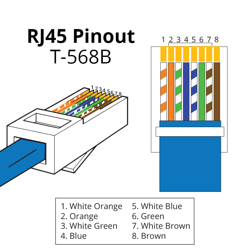
If all cable communication checks have been completed but the inverter still does not detect all batteries, inspect the dedicated CAN cable (RJ45). Verify that the default wiring and pinouts are intact. Some installers may have modified the cable during installation.
DEYE: only pins 4 and 5 are used for inverter-to-battery communication.
VICTRON:
- Verify Power Cable Connections
Examine the photos to ensure all power cables are securely connected. Keep in mind that the wiring setup may vary depending on how many batteries are stacked.
🔋
How to Check if Battery is Working
For Victron ➡ Click here.
For Deye ➡ Click here.
Before adjusting any DIP switch settings, always follow this safety procedure:
-
Turn off the main battery circuit breaker.
-
(If needed) Hold down the reset button until the battery powers off completely.
-
Ensure all batteries are fully OFF, then configure the DIP switches according to the required address settings.
-
Turn the battery circuit breaker back ON to restore power.
To restore functionality and isolate the issue:
-
Disconnect the suspected faulty battery from the stack.
-
Reconfigure and restart the system using only the remaining batteries.
-
If the system resumes normal operation, it is likely that the removed battery is the source of the fault.
This approach helps confirm the impact of the faulty unit and restores partial system function while awaiting replacement or service.
-
Low Battery Voltage
-
BMS Connection Lost
Upon inspection, it was discovered that the DIP switch on the 2nd battery had not been configured properly and the LED alarm indicator was also lit.
Related Articles
Understanding Battery Cell Imbalance
Battery banks configured in parallel are common in solar energy storage systems. While parallel configurations increase amp-hour (Ah) capacity and enable higher energy reserves at a constant voltage, they also introduce a critical challenge: State of ...How to Fix Battery Cell Imbalance (BSL Battery)
A battery cell imbalance may present through unusual SOC (State of Charge) behavior, red LED indicators, or system instability. If one battery in the stack is out of balance, it can cause inconsistent charging and affect overall performance. The goal ...Pylontech Battery – Basic Troubleshooting Guide
This guide outlines the correct wiring, startup, and shutdown procedures for integrating Pylontech US5000 lithium batteries with a Victron inverter system via CAN-bus communication. It is compatible with Victron and Deye hybrid inverters. Quick Check ...Pylontech Battery - Basic Troubleshooting Guide (Batteries not discharging - Battery Monitor [512] Internal Failure Alarm)
Once this is reported by the customer, we must first request for photos of the whole setup to check any wiring/connection anomalies. Then confirm the number of affected batteries by following the steps below 1: On the VRM portal, Go to Remote Console ...Sungrow Troubleshooting
Use this guide a checklist when troubleshooting a faulty Sungrow system. 1. I have reset my system Turn the system off You Sungrow inverter will have the solar panels connected and a AC switch that connects to the switchboard. 1. Turn off the PV ...